Although we (I and my partners) prefer some methods over others, I describe a variety of methods of different kinds for making MBBs, in part because some methods differ in which proteins can be used, or in the number of DNA attachment sites per protein that they allow, and in part because we may encounter unexpected difficulties in our preferred methods, and thus would like to have fallback methods available. (We have other methods or variations not included here for reasons of brevity.)
The methods described cover a variety of levels of difficulty or risk to develop, cost to practice, and level of generality of MBBs that can be made, as well as of implementation techniques. Many applications of DGAP will be made possible even if only one of these methods is implemented. We expect that most of them could eventually be implemented, and we might implement more than one if the new applications made possible by the newly accessible kinds of MBBs justified it.
To develop any of these methods, we expect that we will need to work in an existing lab with the help of researchers and lab technicians experienced in the specific kinds of techniques we will use. Furthermore, many of the specific protocols, described here in general terms, will need to be chosen and developed with expert advice, including protocols for separation (discussed here very generally) and other kinds of characterization and verification (not discussed at all), as well as the synthesis of linker molecules and/or the genetic engineering of core proteins for MBBs, which would be needed for some of the methods.
(Other issues not discussed in this document include the details of the P-sites and the covalent crosslinking between P-sites on different assembled MBBs, the geometry of attachments between MBBs, and any of the specific possible applications of these MBBs assembled using the DGAP process.)
In order to uniquely orient each MBB using the DNA (attached to the C-sites), at least three C-sites are required. Many structures will be easier to build from MBBs with at least 4 C-sites, distributed (very roughly) tetrahedrally, so that the protein can be pulled stably in any direction using the closest three of the four sites. Four C-sites should be sufficient for most structures, but up to eight or so sites could be useful in some cases.
(Attachment of suitably modified DNA to the sulfhydryl groups of cysteines or to the biotin-binding sites of streptavidin are standard techniques [Hermanson 1996].)
It is also possible that specific functionalization of surface lysine residues could be used to form an additional C-site on certain core proteins, after genetic replacement of endogenous lysines and introduction of new lysines at desired positions for C-sites. Similar genetic modifications have been done for other reasons [Gaertner et.al. 1992]. The discussion of lysine functionalization by anhydrides in Hermanson [1996, p. 145] implies that specificity for this residue is possible, though we have not yet investigated this sufficiently.
There is no inherent limit to the number of amino acids that can be modified with this technique, since modified genes can be amplified between sequential replacements, if necessary. Provided that the replacements are isolated surface amino acids, it is likely that the modified protein will fold in the same way as the native one [Handel 1995, personal communication].
For a streptavidin tetramer whose biotin-binding sites are used, the molecule's symmetry (with three 2-fold rotation axes -- less symmetrical than a regular tetrahedron) renders each site indistinguishable, but if one site is chosen arbitrarily, the other three are distinguishable from each other (they are all at different distances from the chosen site); this means that to have only one species of MBB, it is still necessary to produce only one geometrical arrangement of attached DNA sequences, out of the 6 arrangements that would be possible given only that exactly one copy of each DNA sequence is attached to each tetramer.
Some of the methods described here achieve the necessary specificity of DNA attachment by taking advantage of the different distances between different pairs of attachment sites, either during the construction of MBBs, or by separating the correct ones from the others after they have been constructed nonspecifically. One method makes use of site-specific blocking groups, one of site-specific attachment chemistries, and one of the ability to assemble certain multi-protein complexes from distinct subunits.
Other requirements: ability to attach DNA to one site on each of several subunit proteins (using any of the methods mentioned previously, i.e. to an introduced surface cysteine, or to the amino or carboxyl terminus); some knowledge of structure of subunits and complex.
Outline of method:
Attach a different DNA sequence to each subunit in isolation, then mix the subunits so as to reconstitute the complex. Probably necessary to covalently crosslink the subunits to stabilize the complex.
Details:
Attachment methods are as described in Method 2.
Possible problems:
C-sites: the amino terminus, the carboxyl terminus, and the single surface cysteine
Outline of method:
Attach a different DNA sequence to each C-site by using an attachment protocol which affects only that kind of site. (Sequences with no significant complementarity should be used.)
Details:
For all attachments of DNA described in this method, the general strategy will be to modify each C-site (in a way specific for that site) to introduce a functional group not otherwise found on the protein, and then to conjugate the resulting modified protein to DNA (with a suitable functional group attached in a separate prior step).
Attachment of functional groups to cysteines (and the introduction of cysteines by genetic engineering) was discussed in the Introduction. Attachment of functional groups specifically to the amino terminus can be done by mild oxidation of an N-terminal serine or threonine [Fields & Dixon 1968; Geoghegan & Stroh 1992; Gaertner et. al. 1992]. Attachment of functional groups specifically to the carboxyl terminus can be done by reverse proteolysis followed by hydrazone bond formation, under mild conditions [Rose et. al. 1991; King et. al. 1986].
The specific choice of functional groups and final conjugation chemistries have not yet been made, but several alternatives appear to be available [Hermanson 1996]. If each attached DNA and its linker is stable under the procedures for attachment of subsequent DNAs (as is reasonable to expect given the mild conditions of the functionalization procedures referred to), it is likely that the same final conjugation chemistry can be used in each case, with each DNA added before subsequent C-sites are functionalized. If not, it will be necessary to attach all the DNAs at the end and thus to use three different final conjugation chemistries.
Since these methods have less than 100% yield, the correct MBBs should be purified at the end, for example by affinity separation using each required DNA sequence in turn, or gel-retardation (possibly using all complementary sequences at once), or by overall charge or molecular weight (e.g. by DNA-denaturing electrophoresis). (It will probably be desirable to purify the MBBs at various intermediate stages as well, especially during development of the protocols.)
The bases of the flexible portions of the termini (and also the sulfhydryl group of the cysteine) need to have some minimum separation, which I estimate to be 6 to 8 Angstroms, in order to permit use of the resulting MBBs in the DGAP process.
Possible Problems:
Only three attachment sites can be functionalized. For a few applications this will be sufficient (since 3 fixed points are enough to hold the protein in a unique orientation, as mentioned in the Introduction), but for most applications we would prefer to have at least four distinct C-sites.
Possible Variations:
Core protein: streptavidin tetramer (could also use avidin or deglycosylated avidin [Green 1990])
C-sites: four biotin-binding sites
Outline of method (see Figs. 1-5)
Mix streptavidin tetramers in solution with two species of doubly-biotinylated ssDNA (described below; Fig. 5). The two biotins on each ssDNA will be designed to be close enough that they must bind to a pair of binding sites on a single side of a streptavidin tetramer (or to sites on two different tetramers) [Green et. al. 1971]. The desired MBB (Fig. 2) consists of single streptavidin tetramer conjugated to one ssDNA of each species, with a specific one of two possible geometrical arrangements, given that each ssDNA has bound to two sites on one side. Desired arrangement will allow hybridization between parts of the two ssDNAs on a single MBB, which will be impossible in the other arrangement due to different distances between different pairs of biotin-binding sites, or due to two copies of the same species of ssDNA being conjugated to one tetramer. Thus under non-denaturing conditions, only the desired end product particles will consist of just one streptavidin tetramer, conjugated to the right amount of DNA, and with the desired hybridization of some of that DNA; this will allow the correct MBBs to be separated from the others.
Details and discussion
This method takes advantage of the ease of obtaining biotinylated DNA and
attaching it to this protein. (For various reasons (mentioned below) we
may prefer to use either streptavidin, avidin, or deglycosylated avidin;
the following discussion applies in any of these cases.)
This method depends on the symmetric structure of streptavidin (or avidin, which has a very similar structure) and the specific arrangement of its biotin-binding sites (or more precisely, the points at which bound biotin protrudes from the protein) [PDB files 1SLF and 1STP (click here to see them via a Java applet), RCSB Protein Data Bank; Green 1990, Green et. al. 1971, Livnah et. al. 1993, Hendrickson et. al. 1989.].
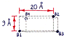
Figures 1a-d depict the structure of streptavidin in a schematic form.
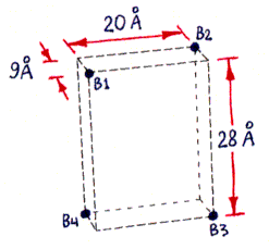
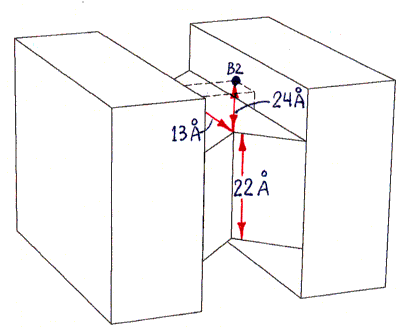
Fig. 1a and 1b
Fig. 1a (corresponding top view shown in Fig. 1c) shows the approximate locations of the bound-biotin carboxyl groups ("biotin binding sites" B1-B4), which are on alternate vertices of an imaginary rectangular solid, embedded in the streptavidin tetramer, with the dimensions shown. Part of this solid, showing site B2, is also visible in Figs. 1b and 1d. (Fig. 1d also shows site B1.) (These dimensions were computed from measured inter-atomic distances in the PDB files referred to in the main text, but the atoms used to represent the binding sites were not parts of the carboxyl groups themselves, but were sulfur atoms within sulfate ions bound in approximately the same locations. The resulting error in binding site locations is estimated to be less than 1 A (Angstrom) in any direction, based on comparisons between PDB files containing either bound sulfate or bound biotin.)
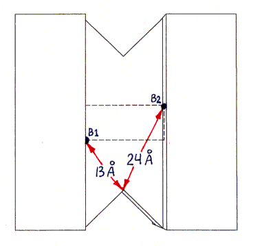
Fig. 1b (corresponding top view shown in Fig. 1d) shows a highly schematic view of a streptavidin tetramer, along with the estimated length of each segment of the shortest paths (over the protein surface) which connect various pairs of binding sites. All path segments not shown are related by symmetry to one of the ones shown. (The paths themselves can be best seen in Fig. 2, although only the shortest path, from B1 to B3, is represented there.)


Fig. 1c and 1d : Top Views
The actual shape of the tetramer looks quite different from the shape shown, but the locations and lengths of the shortest over-surface paths (as visually inferred from the PDB file) are approximately correct. The figure has the same 2-fold rotational symmetries as the tetramer, as well as, for simplicity of presentation, additional mirror symmetries (of the overall shape only, not of the binding site locations) which the tetramer does not have.Sites B1 and B3 are connected by three segments in succession of lengths 13 A, 22 A, and 13 A (the last segment is on the bottom and thus not visible in the figure). An alternative path from B1 to B3, going behind the protein (not shown), is much longer, with segment lengths of 24 A, 22 A, and 24 A.
Sites B1 and B4 are connected by segments of lengths 13 A, 22 A, and 24 A (as well as by another path of the same length behind the protein, not shown, with segment lengths 24 A, 22 A, 13 A).
All other pairs of sites are related by symmetry to one of these pairs (or to the B1-B2 pair, with a much shorter single-segment path of 22 A, not shown).
The procedure described in the main text depends on the difference between the shortest-path length connecting sites B1 and B3, and that connecting sites B1 and B4. This difference is estimated as 11 A (24 A minus 13 A). The accuracy of this estimate depends only on the accuracy of the 24 A and 13 A segment length estimates (since the 22 A segment and one of the 13 A segments are shared by both paths being compared).
The actual path taken by the ssDNA backbones and dsDNA helix (as shown in Fig. 2) would of course be longer due to the DNA's necessary separation from the protein surface, adding perhaps 4 A per corner turned, but this effect is approximately the same for both paths. The effective path lengths will have to be determined by experiment, as discussed in the main text, but it is likely that the actual path-length difference will be almost as great as that for the idealized paths shown in this figure.
We use the following facts about the structure of the streptavidin tetramer (Fig. 1) (a modified PDB file showing the features discussed is available on request):
Figures 2a-d depict the structure of desired end product MBB in a schematic form.
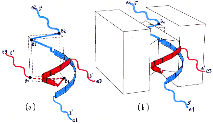
Fig. 2a and 2b
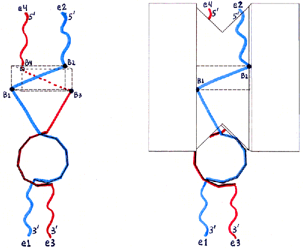
Fig. 2c and 2d : Top Views
Fig. 2 uses the same views as Fig. 1, but shows the locations of ssDNA and dsDNA in the desired product of the initial mixing step (with the hybridization which will only be possible for this product). ssDNA12 (see Fig. 5 in text for nomenclature) is shown in blue, and ssDNA34 in red. The ssDNA ends are labelled with 3' and 5' and with e1-e4 (for end 1 through end 4) as in Fig. 5. The backbones of the hybridized dsDNA region are shown as small rectangles forming a double helix (with the major groove facing the protein surface). The segments which remain unhybridized are shown as straight or wavy lines depending on whether they will be stretched to almost their maximal lengths (true for the ssDNA bases shown as dots in Fig. 5) or will remain free to move (true for the ssDNA bases shown as X's in Fig. 5). The wavy lines (ssDNA X bases) are the ones intended to be left free for further hybridization when the product MBB is assembled with other MBBs in the DGAP process.
The two species of doubly-biotinylated ssDNA to be attached have structures as follows:
Figure 5:

name                    structure (with end labels)
-------   --------------------------------------------------------------
ssDNA12:  end 1 ->  3'XXXXXXXXXXxxxxxxx....b.....bXXXXXXXXXX5'  <- end 2

ssDNA34:  end 3 ->  3'XXXXXXXXXXxxxxxxx....b.....bXXXXXXXXXX5'  <- end 4
Key to symbols:
(Biotin is often attached to DNA with a long linker arm; in the structures above I am assuming it can be attached directly into the ssDNA backbone with no additional linker arm. This is a reasonable assumption given the wide range of biotin attachment configurations in use. If this is not true we will need to use linkers other than ssDNA bases in place of some of the DNA bases shown by periods above.)
Figure 3 shows some of the species of conjugates that can be obtained as products of the initial mixing step. (As mentioned previously, the separation between the two biotins on each ssDNA molecule is kept short enough that, if both biotins bind to one streptavidin tetramer, they must bind at either sites 1 and 2, or at sites 3 and 4, since all other pairs of sites are separated by a greater distance than the biotins are.)
Figure 3a-h depict products of initial mixing step (assuming no dimerization).

Fig. 3a and 3b : Desired product (assuming no dimerization).
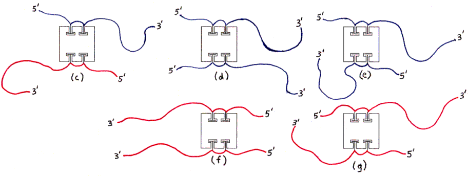
Fig. 3c through 3g : Undesired products with right amount of DNA (hybridization not possible without forming aggregates).
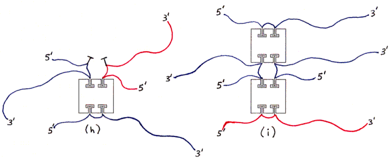
Fig. 3h and 3i : Undesired products with wrong amount of DNA (examples).
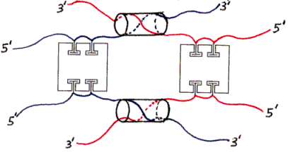
Figure 4. Dimer of undesired products (one example).Figs. 3 and 4 show various products of the initial mixing step (and subsequent hybridization). The individual subfigures are discussed in the main text.
The ssDNAs are colored and labelled as in Fig. 2. Hybridized dsDNA regions are shown as colored ssDNA backbones on the surface of an imaginary cylinder representing the shape of the helix. Biotin is shown as a small T-shape.
Streptavidin tetramers are shown even more schematically than in the previous figures, as squares with four T-shaped holes representing biotin-binding sites. These squares are oriented as if the rectangular solid in Fig. 1a was seen from the left side (not from the front or back). The biotin sites in the tetramers shown in Figs. 3a and 3b are labelled B1-B4 accordingly. Note that four different labellings would be valid, due to the symmetry of the tetramer; in particular, Fig. 3b is identical to Fig. 3a if rotated 180 degrees around a vertical axis. (The other axes of 2-fold rotational symmetry are the horizontal axis and the axis perpendicular to the plane of the figures.)
It will be desirable to do the mixing at sufficiently low concentrations of all ingredients that each ssDNA molecule or streptavidin tetramer usually encounters only one other molecule at a time, to maximize the chance that both biotins of one ssDNA molecule bind to the same streptavidin tetramer. (A low concentration is also necessary to avoid aggregation of streptavidin due to low solubility.) The initial mixing should probably be done under denaturing conditions for DNA, so that individual ssDNA molecules are usually encountered separately, but we will determine by experiment whether this is actually better, and which ingredients should be in excess, for maximizing the yield of the desired product and for ease of the final separation steps.
For ease of discussion, I will describe the separation in two steps even though one combined step may suffice. The first step will remove all structures other than the ones with exactly one protein and two ssDNAs per particle. (Two such undesired particles are shown in Figs. 3h and 3i.) (We have not yet determined which separation technique to use. Niemeyer et. al. [1994] have demonstrated separation of streptavidin-DNA conjugates carrying varying numbers of DNA molecules by both ion-exchange chromatography and non-denaturing PAGE. Isoelectric focusing might also be expected to be useful. Niemeyer et. al. [1994] have also demonstrated gel-retardation of streptavidin-DNA conjugates by complementary DNA, which might be necessary for separation of streptavidin-PNA conjugates if we use PNA for other reasons.)
The remaining particles include some with two copies of the same ssDNA (Figs. 3d-3g), and some with one ssDNA of each kind (Figs. 3a-3c); of the latter, some have the desired geometrical arrangement of ssDNA (Figs. 3a and 3b) and some have the other arrangement (Fig. 3c). (All arrangements not shown are equivalent by symmetry to some arrangement which is shown.)
In order to distinguish between these species, we will design the ssDNA sequences so that sequences 1 and 3 (where sequence n means the DNA between end n and the nearest biotin) can hybridize as shown in Figs. 3a and 3b (and Fig. 2), but only if the biotins nearest to ends 1 and 3 are attached to sites 1 and 3 (or the symmetrically equivalent pairs of sites, 3 and 1, 2 and 4, or 4 and 2). This is possible because these pairs of sites are significantly closer (along a path over the protein surface) than the other pairs to which these biotins could be attached (see Fig. 1). (The sensitivity of using the presence or absence of hybridization to distinguish these inter-site distances is discussed below.)
Nondenaturing electrophoresis can be sensitive to differences in hybridization, so we should be able to detect this difference directly, perhaps in the same separation step in which we remove particles with the wrong amount of DNA or protein. Also, particles whose 1 and 3 strands (or two 1 strands or two 3 strands) are prevented from hybridizing to each other are likely to form dimers (or larger polymeric aggregates) in which strands attached to different proteins hybridize (Fig. 4); such particles would certainly be separable in the initial step.
The end result will be the separation of the desired product from all
other products of the initial mixing step. In some applications the product
can be used directly (in spite of its attached double helix). For other
applications we may want to alter the ssDNA using further routine methods,
such as ligation to dsDNA with a long overhang (though whether the ligase
will be sterically hindered is unknown). Other possible modifications to
the final MBBs are discussed below.
The dehybridization of one base pair of the dsDNA region would allow
the total length of the ssDNA/dsDNA combination to increase by only about
2.5 A (the difference between the length of ssDNA per base, 5.9 A, and
the rise of one base pair in dsDNA, 3.4 A). Thus, to make up for the 11
A difference, at least 4 of the base pairs would have to separate, so the
two ssDNA strands could not hybridize when their ends were separated by
the longer path length. (Both ssDNA and dsDNA can be stretched to 7 A per
base under sufficient tension [Smith 1996, Saenger
1984], but this seems unlikely to be preferred over a lack of hybridization.)
Possible errors in estimates of inter-site distances:
I estimated over-surface distances on the protein by visual inspection of 3D protein models based on PDB files (to guess the shortest paths between attachment sites; Fig. 1) and calculation of line-of-sight distances between specific atoms appearing to lie on those paths. (I added sufficient length to account for the actual path of a chain of bonded atoms being separated from the surface by 4 A due to steric hindrance.) (Some parts of the actual paths for the ssDNA segments must be slightly bent outwards compared to the calculated paths, but this effect appears to be about the same for each path.)
There are numerous sources of possible error in this estimation. Furthermore, I have neglected consideration of possible interactions between the DNA and protein other than steric hindrance, notably electrostatic forces, which might strongly favor some paths and oppose others. Thus the actual threshhold lengths for hybridization will have to be experimentally determined. (I have developed outlines (not included here) of preliminary experimental protocols to determine the path lengths necessary for hybridization, in which each path's required length of DNA can be determined independently. Therefore it should not be necessary to try all pairs of path lengths in combination. Given the range of likely path lengths, a few trials in succession should suffice to measure them, once the experimental technique itself is debugged.)
Since the estimate of path-length-difference is more reliable than the estimates for the path lengths themselves (as discussed above), and since this difference is sufficient to prevent hybridization of 4 base pairs, the margin of error suggests that this method is likely to be workable.
If it appears that electrostatic effects are causing problems, we have the option of using NeutrAvidin (a form of deglycosylated avidin available from Pierce Chemical Co., with an isoelectic point much closer to pH 7 than streptavidin), and/or PNA (which is uncharged), as well as increasing the ionic strength.
Stability of biotin-streptavidin attachment:
The biotin-streptavidin interaction has a half life for exchange of biotin of only a few days at 25 degrees C (precise value depends on pH) [Green 1990, Jones & Kurzban 1995]. At 4 degrees C the half life is much longer (undetectable, according to Jones & Kurzban [1995]). The biotin-avidin interaction is much more stable, with a half-life of 200 days at pH 7 and 25 degrees C [Green 1990]. It may be desirable to stabilize streptavidin-based MBBs with additional covalent crosslinks between the protein and the biotin-DNA conjugate, or to stabilize assemblies of MBBs by covalent crosslinks between the proteins (as assumed will be desirable in general for use of the DGAP process). Details of possible covalent crosslinks have not been developed. Genes of both avidin and streptavidin are available for genetic engineering if necessary for surface residue replacements [Green 1990, Chandra & Gray 1990]. (Having to genetically engineer the protein would remove some of the advantage of this method in ease of development, compared to some of the other ones discussed here, which can furthermore be applied to a wider variety of proteins. However, once the modified protein was developed, this method would still be easier to practice than the others when many MBBs differing only in DNA sequences were desired.)
Stability of tetramers:
We cannot exclude the possibility that the individual monomers in streptavidin or avidin tetramers might rearrange [Jones & Kurzban 1995], or even exchange between proteins, at some slow rate, rendering our "building blocks" unstable. If so, we will have to stabilize the tetramers with covalent crosslinks of some kind, such as disulfide bonds between genetically-introduced cysteines.
Oligo-tetramers:
Aggregation of streptavidin tetramers into higher-order forms, perhaps covalently crosslinked, has been reported [Bayer et. al. 1989]. If necessary, we can remove these from our starting materials by gel filtration [Bayer et. al. 1990]. However, since the final separation must remove tetramers linked intermolecularly by doubly-biotinylated ssDNAs, it will probably not be necessary to purify these from the starting material in a separate step.
Alternative separation methods:
The two ssDNA sequences shown are of the same length, but it would be possible to use sequences of two different lengths, which would aid in the separation of the particles with two copies of one sequence, and would provide more information about the yield of each form (shown in Fig. 3) after the initial mixing.
Application to other proteins:
An analogous method should be possible for other tetrameric proteins with the same 222-point symmetry as streptavidin, using a DNA- attachment method other than biotin binding. Low protein concentration will favor attachment to one protein of both conjugation groups on each ssDNA during the initial mixing/binding step, even if this conjugation is slow and possibly reversible. Subsequent steps will be precisely analogous except for the required DNA lengths being different.
Stabilization of hybridized region of MBB:
It may be possible to stabilize the hybridized dsDNA region in the final MBB with intra-base-pair disulfide bonds [Goodwin et. al. 1994] in case this would help with assembly of several MBBs.
Digestion of hybridized region with restriction enzymes:
Alternatively (or in addition) we may want to digest the hybridized dsDNA region with a restriction enzyme, in which case that region will have to be made at least 8 base pairs long [catalog, New England Biolabs, 1996/97, p. 238], and we will have to test for steric hindrance of the enzyme by the core protein. (If steric hindrance occurs, this technique could probably still be used if restriction itself was used as the test for correctness of an MBB.) The hybridized regions left after restriction would be sufficiently short (4 base pairs minus half of the sticky-end length made by the enzyme) not to interfere with hybridization of the resulting ssDNAs to ssDNAs introduced later, e.g. from other MBBs in a DGAP assembly. Although the restriction-shortened ssDNAs would have the same sequences for short lengths at their ends (due to the restriction site being palindromic), they could still be different farther from the end, and thus be specific for hybridization to different external sequences.